The inversion of camera projection is a common task in 3d graphics. The projection of the camera maps a 3d scene to the 2d image plane. So every surface point in the 3d scene that is visible from cameras point of view has a corresponding pixel on the image plane.
I see two tasks in inversion of projection. First one can reconstruct the projection ray that belongs to a certain pixel. That is a basic task. Second one can compute the 3d coordinates of the corresponding surface point that is located somewhere on the projection ray. You will either need a depth coordinate (z) to compute the surface point or do a raycast on the objects of your 3d scene with the projection ray.
We focus here on reconstructing the projection ray only. This approach avoids inversion of projection matrix. All examples are shown using THREE.js framework.
Reconstruct the projection ray
In order to reconstruct the projection ray for a given pixel we consider the following thoughts: The projection ray is the inverted beam of light that has travelled from a surface point into the camera. The projection ray originates at the position of our camera what is equal to the origin of the camera coordinate system. Further the projection ray penetrates through the given pixel in the image plane and points into the 3d scene. So we have the origin of the ray and another point lying along the ray, what is enough to define the ray by origin and direction. We want to reconstruct the ray in camera coordinates. It might be transformed to world coordinates easily if needed.
We start by having our origin of the ray given by the origin of the camera coordinate system:
ray.origin = new THREE.Vector3(0.0, 0.0, 0.0);
To get the direction of the ray we need our given pixel coordinates in camera coordinate system as well. A pixel is a 2d element given by p = (x, y). We assume here that pixel coordinates are integer coordinates somewhere in the range from 0 to the number of pixels your viewport has (rendering area e.g. window) respectively for x and y direction. That should be the standard situation. We now have to transform p successively from window coordinates through some coordinate systems to finally come to camera coordinates.
NDC coordinates
We get Normalized Device Coordinates (NDC) by inverting the so called viewport transformation on our given window coordinates. NDC have x and y coordinates defined both in interval of [-1, 1]. Note that we neglect the z coordinate here which normally comes from the 3d surface point and is transformed by projection as well. We just don’t need to trace it back for inverted projection here, as we take the pixel p to be on the image plane where z is known.
We do transformation back to NDC in two steps. First we put coordinates of p into the interval [0, 1], what might be considered relative window coordinates. This is done by a simple division with the width/height of the viewport in pixels:
	var relativeWindowCoords = new THREE.Vector2();
	relativeWindowCoords.set(
		p.x / viewport.width,
		p.y / viewport.height
	);
Now we have coordinates in the interval [0, 1]. In a second step we apply a combined scaling and translation now to fit into interval [-1, 1]. First we scale by factor of 2 which yields an interval of [0, 2]. Than we have to translate this interval by -1 which gives the wanted interval of [-1, 1]. A function windowToNDC doing the entire transformation might look like this:
    function windowToNDC(p){
        return new THREE.Vector2(
            (p.x / viewport.width) * 2.0 - 1.0,
            (p.y / viewport.height) * 2.0 - 1.0
        );
    };
Attention: The application of the upper formula comprises a common pitfall. In most 2d applications the origin of the window coordinate system is in the down left corner of the window with the y axis pointing downwards from top to bottom. Most 3d applications by contrast have their coordinate systems (NDC, camera coordinates etc.) defined with y axis pointing upwards from bottom to top. So if you process mouse events from your window system you sometimes have to be careful and flip the y-axis to properly transform the window coordinates in your 3d application. The easy solution to this problem is that you invert the y component of the window coordinates:
yFlipped = viewport.height - event.y;
You can also put this directly into the windowToNDC function:
    function windowToNDC(p){
        return new THREE.Vector2(
            (p.x / viewport.width) * 2.0 - 1.0,
            (p.y / viewport.height) * -2.0 + 1.0  // inherently flip y-axis here
        );
    };
Camera Coordinates
From NDC you can now transform p to the camera coordinate system also called eye coordinate system. The basic idea here is that we have p.x, p.y in relative coordinates (NDC) in [-1, 1] on the image plane and transform them to absolute coordinates using their mathematical relation to the extents of the image plane measured in camera coordinates. The origin of the NDC system is equal to the center of the image plane. All points defined in NDC with x = -1.0 are on the left border of the image plane. All points defined in NDC with y = 1.0 are on the top of the image plane and so on.
The extents of the image plane in camera coordinates is sometimes given by the left (l), right (r), top (t), bottom (b) parameters for the near clipping plane when defining a view frustum (Note: near clipping plane is equal to image plane). These parameters are not coordinates but measures of length. For a symmetrical frustum we have l = r and t = b. With l given for a symmetrical frustum we get p.x in camera coordinates easily: pEye.x = p.x · l. Just a multiplication – it can be so simple :).
In most cases the viewing frustum is not defined by left, right, top, bottom parameters for the near plane but by the so called field of view. This is the viewing angle of the camera in y-direction. The corresponding field of view in x-direction is well defined by the given aspect ratio for the camera. The extent of the image plane is computed from the half field of view, the aspect ratio and the image plane depth (-n). The math and parameters needed are explained in the following illustration.
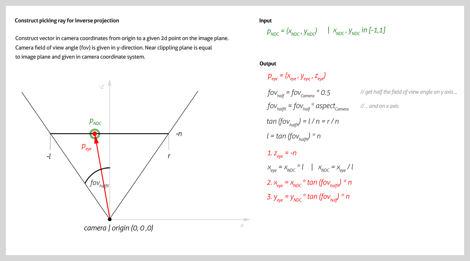
The above illustration uses the depth of the image plane -n for computation. Note that this is negligible. Computation is easier if you put the depth of pEye to pEye.z = -1. pEye is than not necessarily a point on the image plane any more (only if n == 1). But it is still a point on the projection ray and the math is the same. You can leave out every occurrence of n in the above formula as it is equal to 1. The following Javascript function uses this algorithm to reconstruct the projection ray.
    function getProjectionRay(p){
        var rayOrigin = new THREE.Vector3(0.0, 0.0, 0.0);
	var ndcCoordinates = windowToNDC(p);

        // we can calc a ray in camera coordinates through the image plane, even
        // without knowing near plane, just with the field of view of the camera
        // and the normalized device coordinates
        var FOVyHalf = THREE.Math.degToRad(my.camera.fov * 0.5);
        var tanFOVyHalf = Math.tan(FOVyHalf);
	var tanFOVxHalf = tanFOVyHalf * my.camera.aspect;
        var rayDir = new THREE.Vector3(
            ndcCoordinates.x * tanFOVxHalf,
            ndcCoordinates.y * tanFOVyHalf,
            -1.0
        );
        rayDir.normalize();

        return new THREE.Ray(rayOrigin, rayDir);
    };
Finally we have the resulting coordinates pEye of the given pixel p transformed to camera coordinate system. The direction of the projection ray is now defined by its origin and pEye.
Autor: Michael Keutel | 10.04.2015